The Dark Room Timer circuit described here provides a pleasant musical tone in your darkroom at 1-second intervals. The circuit takes up very little space and can be easily converted into a metronome.
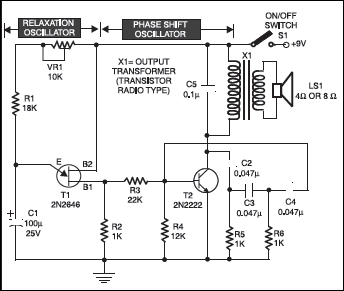
Unijunction transistor T1 functioning as a relaxation oscillator triggers phase-shift audio oscillator circuit turning it on and off. Capacitor C1 is charged through VR1 and resistor R1, the emitter voltage of UJT rises toward the supply voltage.

Fig – Dark Room Timer circuit
The circuit can be broadly divided into three functional blocks: the Relaxation Oscillator, the Phase-Shift Oscillator, and the Output Stage.
1. Relaxation Oscillator (Q1 – 2N2646 Unijunction Transistor)
The first stage is a unijunction transistor (UJT) based relaxation oscillator, utilizing the 2N2646 (T1). This type of oscillator is known for its ability to generate sawtooth or pulse waveforms.
- Operation: Capacitor C1 (100µF) charges through the series combination of R1 (18KΩ) and the variable resistor VR1 (10KΩ). As C1 charges, the voltage across it increases. When the voltage across C1 reaches the peak point voltage of the UJT, the UJT turns on, causing C1 to rapidly discharge through B1 (Emitter to Base1) and the internal resistance of the UJT. Once the voltage across C1 falls below the UJT’s valley point voltage, the UJT turns off, and the cycle repeats.
-
Frequency Control: The charging rate of C1, and thus the oscillation frequency, is primarily determined by the time constant (R1 + VR1) * C1. The variable resistor VR1 allows for manual adjustment of the oscillation frequency, enabling control over the pulse repetition rate. This stage generates a periodic trigger signal, a fundamental characteristic of its “clocker” or timing function.
2. Phase-Shift Oscillator (Q2 – 2N2222 BJT)
The second stage is a transistor-based phase-shift oscillator, employing a 2N2222 bipolar junction transistor (BJT) (T2) in a common-emitter configuration.
- Operation: This oscillator relies on a positive feedback loop where the output signal is fed back to the input, but with a specific phase shift. The network comprising R3 (22KΩ), R4 (12KΩ), R5 (1KΩ), R6 (1KΩ), and capacitors C2, C3, C4 (all 0.047µF) forms the phase-shifting network. Each RC section contributes approximately 60 degrees of phase shift. With three such sections, a total phase shift of 180 degrees is achieved. When combined with the inherent 180-degree phase shift provided by the common-emitter amplifier (T2), the total phase shift around the loop becomes 360 degrees (or 0 degrees), satisfying the Barkhausen criterion for oscillation.
- Interaction: The output pulses from the relaxation oscillator (from the emitter of T1) serve as an input or trigger to the base of T2. This effectively modulates or gates the phase-shift oscillator. Instead of continuously oscillating, the phase-shift oscillator’s tone is activated or “burst” by each pulse from the relaxation oscillator. This results in an audible “tick-tock” or “clocker” sound where the “tock” is a short burst of the phase-shift oscillator’s tone.
3. Output Stage
The combined and modulated audio signal from the phase-shift oscillator’s collector is fed into an output transformer (X1) and subsequently to a loudspeaker (LS1).
- Transformer (X1): The output transformer, specified as a “transistor radio type,” serves two primary functions:
- Impedance Matching: It matches the high output impedance of the transistor amplifier to low impedance of the loudspeaker, maximizing power transfer.
- Audio Coupling: It provides AC coupling to the loudspeaker while blocking the DC component, preventing DC current from flowing through the speaker coil, which could lead to damage.
-
Loudspeaker (LS1): The loudspeaker converts the electrical audio signals into audible sound waves. Capacitor C5 acts as a coupling capacitor, ensuring AC signal reaches the primary of the transformer, preventing DC bias from affecting its operation.
Power Supply
The Dark Room Timer circuit operates from a single +9V DC supply, typically provided by a 9V battery. This makes the device portable and suitable for standalone applications.
This dual-oscillator configuration can be utilized in various straightforward applications, including:
- Educational Demonstrator: Ideal for teaching fundamental principles of relaxation oscillators, phase-shift oscillators, and their interaction.
- Simple Metronome: By adjusting VR1, the “tick” rate can be controlled.
- Dark Room Timer/Alarm: Can generate a repetitive audible signal for basic timing or alert functions.
- Novelty Sound Generator: For creating unique, rhythmic sound effects in simple electronic projects.
