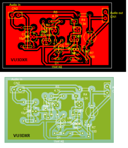
VK3YE’s AGC circuit for ubitx
An ubitx AGC board is a circuit board that can be installed in a ubitx transceiver to provide automatic gain control (AGC). AGC is a feature that automatically adjusts the gain of the transceiver’s amplifier to maintain a constant audio output level, regardless of the strength of the received signal. This can help to prevent clipping and distortion. It can also improve the overall sound quality of the transceiver.
There are a number of different AGC boards available for the ubitx. Some of these boards are designed to be installed by a qualified technician. The cost of an AGC board varies depending on the features and the manufacturer.
VK3YE’s LED-LDR AGC Circuit for uBITX
VK3YE (Peter Parker) developed a clever “non-invasive” AGC (Automatic Gain Control) circuit specifically designed for the uBITX transceiver. The circuit uses a conventional audio AGC circuit which drives a LED that is optically coupled to a Light Dependent Resistor (LDR). As the signal rises the LED emits more light and the LDR’s resistance drops.The LDR is connected in parallel with the volume control. In effect, an automatic volume control. This is effectively an automatic RF attenuation circuit to provide AGC functionality for the uBITX. Points connected to the volume control are in parallel with existing wiring.
The circuit operates by:
- Using a conventional audio AGC circuit to detect signal levels
- Driving an LED based on the detected signal strength
- The LED light affects an LDR (Light Dependent Resistor)
- The LDR resistor works in conjunction with the 3.3K to lower the signal amplitude into the volume control
Key Components and Performance
Circuit function depends on using an LDR with an appropriate resistance range. My junk box LDR exhibited 40k to 400k ohms. Too high – indicating that proper LDR selection is critical for optimal performance.
Users have been pleased with the somewhat unusual VK3YE AGC circuit, that uses a LDR and LED pair, as it nicely removes the top of large signals.
S-Meter Addition
A meter connected in series with the LED via a current limiting resistor becomes an effective S-meter. VK3YE has suggested measuring current in parallel with the LED that drives the AGC action, but he found this gave little indication of relative signal strength. In fact, it works much better measuring current in series with the LED.

VK3YE’s AGC circuit uses a conventional audio AGC circuit which drives a LED that is optically coupled to a Light Dependent Resistor (LDR). As the signal rises the LED emits lighter and the LDR’s resistance drops. The LDR is connected in parallel with the volume control. In effect, an automatic volume control. As Drew VK3XU once wrote, ‘neat, not gaudy’. A meter connected in series with the LED via a current limiting resistor becomes an effective S-meter. Circuit function depends on using an LDR with an appropriate resistance range.
Installation Notes
For installation on BITX40/uBITX, the 3.3K resistor in Peter’s circuit doesn’t exist in the BITX40 and would have to be added between C115 and the high side of the volume control.
The LED photoresistor AGC provides attenuation from mere resistance so there is minuscule distortion , making it an elegant solution for AGC in these transceivers.
This circuit became popular among uBITX users as a relatively simple modification that addresses the lack of built-in AGC in the original uBITX design, which could cause discomfort when strong signals suddenly appeared while listening to weaker ones.