Have you ever wondered whether those crystals sitting in your electronics parts drawer are still functional? As electronics enthusiasts, we often accumulate various components over time, including crystal oscillators that are essential for timing circuits in microcontrollers, radios, and digital systems. Rather than guessing their condition, you can build this simple yet effective UJT crystal checker circuit to test them reliably.
UJT Crystal Checker
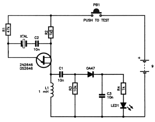
A UJT crystal checker is a specialized test circuit that uses a unijunction transistor (2N2646 or 2N2648) configured as a feedback oscillator. This clever design allows you to quickly verify whether crystal oscillators are functioning properly without complex equipment. The circuit generates visual feedback through an LED indicator, making crystal testing straightforward and immediate.
How the Circuit Works
The UJT crystal checker operates on a simple but effective principle:
Feedback Oscillation: The 2N2646/2N2648 UJT creates a feedback oscillator circuit. When a functional crystal is connected, it provides the precise frequency reference needed for stable oscillation.
RF Detection: The RF choke (L1 – 1mH inductor) in the base 1 lead develops RF voltage across the crystal oscillates, creating the conditions necessary for detection.
Visual Indication: The OA47 germanium diode rectifies the RF voltage, charging capacitor C3. This voltage forward-biases LED1, causing it to illuminate when a good crystal is detected.
Sensitivity Control: The circuit can detect crystals operating on less than 1mA of current, making it sensitive enough for most standard crystals while being powered by a simple 9V battery.
UJT Crystal Checker –Circuit Components Breakdown
- 2N2646/2N2648 UJT: The heart of the oscillator circuit
- C1 (10n): Coupling capacitor for the crystal connection
- C2 (10n): Timing capacitor for the UJT oscillator
- C3 (10n): Filter capacitor for LED drive circuit
- L1 (1mH): RF choke inductor
- OA47: Germanium diode for RF detection and rectification
- LED1: Visual indicator for crystal status
- R1, R2: Biasing resistors for the UJT
- PB1: Push-to-test button for circuit activation
- 9V Battery: Power source
Frequency Range and Limitations
This UJT crystal checker works effectively with crystals in the 7-8 MHz range, though the exact frequency response depends on the individual UJT characteristics. The circuit is particularly well-suited for:
- Computer clock crystals
- Radio frequency crystals
- Microcontroller timing crystals
- General-purpose oscillator crystals
For crystals with fundamentals below this range, the circuit will still function but may show reduced sensitivity. It’s also excellent for testing overtone crystals, TV crystals, and other low-frequency oscillators.
Building Tips and Considerations
Crystal Socket Connection: Use a parallel arrangement for crystal socket connections, allowing you to test various crystal packages including HC-49 and other standard formats.
Pigtail Crystals: For pigtail-leaded crystals, simply press the push-button for a few seconds and observe the LED. A bright LED indicates a functional crystal.
Power Efficiency: The circuit draws minimal current from the 9V battery, making it suitable for portable use in the workshop or field.
Component Substitutions: While the 2N2646 is specified, the 2N2648 UJT can be substituted with similar performance characteristics.
Circuits – Simple Crystal Tester
Build Your Own 90MHz Crystal Controlled FM Transmitter
