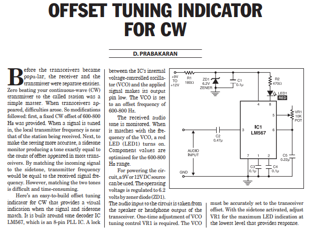
An NE567 tone decoder, tuned to the transceiver`s CW offset frequency, ensures that the transceiver will be transmitting on the same frequency as the received CW signal. Simply tune the transceiver so that the LED lights. Eight to 13 Vdc is required; this can be taken from the transceiver supply or an extra battery. Audio is taken from the speaker or headphone output.This is a fantastic little circuit for amateur radio enthusiasts, particularly those who enjoy operating Morse code (CW).
For anyone who loves the art of Morse code communication (CW) on the amateur radio bands, precise tuning is paramount. Hearing a faint “dit-dit-dah” in the noise and being able to quickly zero-beat (match frequencies) with the transmitting station can be the difference between a successful QSO (contact) and a missed opportunity. While many modern transceivers offer fancy digital tuning aids, there’s a timeless charm and immense utility in a dedicated, simple analog indicator.
The Challenge of CW Tuning
When you receive a CW signal, your transceiver’s receiver converts the incoming radio frequency (RF) signal into an audio tone that you hear in your headphones or speaker. The pitch of this audio tone depends on how close your receiver’s frequency is to the incoming signal’s frequency, and also on your transceiver’s CW offset. Most CW operators prefer a consistent “sidetone” (the tone their own transmitter generates when keying) and aim to tune incoming signals to match that comfortable pitch, typically around 500-800 Hz.
While a good ear can do the job, it’s not always easy, especially with weak signals, QRM (interference), or if you’re not blessed with perfect pitch. This is where an offset tuning indicator becomes incredibly useful.
This circuit Offset tuning indicator for CW leverages the power of a Phase-Locked Loop (PLL) tone decoder, specifically the LM567 IC, to provide a visual indication when you’ve hit that sweet spot – your desired CW offset frequency.
Let’s break down the key elements:
- Audio Input: The circuit takes its input directly from your transceiver’s audio output (e.g., speaker line or headphone jack). This means it’s non-invasive and can be easily added to almost any rig.
- LM567 Tone Decoder: This is the heart of the circuit. The LM567 is a highly versatile integrated circuit designed to detect a specific frequency within a range. By carefully selecting external resistors (R1, R2) and capacitors (C1, C2, C3), the LM567 is “tuned” to your desired CW offset frequency (e.g., 700 Hz).
- LED Indicator: When the audio tone from your receiver matches the frequency that the LM567 is set to detect, the LM567’s output goes low, illuminating the LED (LED1). This provides an immediate, clear visual cue that you are precisely tuned to the incoming CW signal’s desired offset.
- Potentiometer (P1): This adjustable resistor is crucial for fine-tuning the circuit. It allows you to precisely calibrate the LM567’s detection frequency to match your transceiver’s sidetone or your preferred listening pitch.
-
Simple Power Supply: The circuit Offset tuning indicator for CW requires a modest DC voltage (typically 8-13V), which can often be sourced directly from your transceiver’s accessory jack or a small external battery. The 1N4001 diode provides reverse polarity protection, a thoughtful addition for any DIY project.

