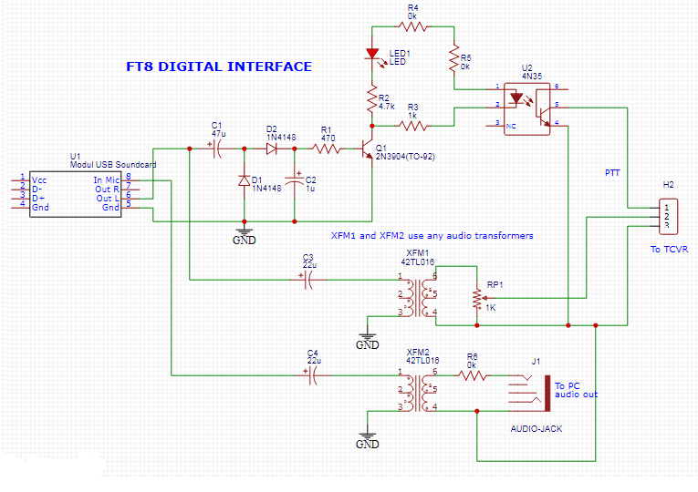
Dive into Digital Modes – Build Your Own FT8 digital Interface!
FT8 has revolutionized amateur radio digital communications with its weak signal capabilities and automated operation. To operate FT8 effectively, you need a reliable interface between your computer and transceiver. This blog post examines a well-designed FT8 digital interface circuit that provides both audio coupling and PTT (Push-to-Talk) control.
FT8, this highly efficient digital mode, part of the WSJT-X suite, allows for reliable communication even with very low power (QRP) and challenging band conditions. It’s time-synchronized, meaning everyone transmits and receives in precise 15-second intervals. This makes it incredibly efficient, allowing for QSOs (contacts) even when signal levels are below the human ear’s ability to discern them. But to get on FT8, you need a way to connect your computer (which runs the FT8 software) to your transceiver. That’s where a FT8 Digital Interface comes in!

To operate FT8 (or any other soundcard-based digital mode like PSK31, RTTY, etc.), your computer needs to:
- Send audio to the transceiver: The software generates digital “tones” that your radio transmits as RF.
- Receive audio from the transceiver: The radio’s received signals are fed back to the software for decoding.
- Control the transceiver’s PTT: The software needs to tell the radio when to switch between transmit and receive modes.
A digital interface handles these critical connections, often with galvanic isolation to protect your expensive radio and computer.
The heart of the interface is a USB sound card module that connects directly to your computer via USB. This provides:
- Digital-to-analog conversion for transmit audio
- Analog-to-digital conversion for receive audio
- USB power for the interface circuit
- Isolation from computer ground loops
U1 – Modular USB Soundcard
This is the bridge between your computer’s USB port and the analog audio signals. Your computer treats it like an external sound card.
- “In Mic +” / “In Mic -” (Pins 1 & 2): These are the audio input from the transceiver to the soundcard (for decoding received FT8 signals).
- “Out R” / “Out L” (Pins 3 & 4): These are the audio outputs from the soundcard to the transceiver (for transmitting FT8 signals). You’ll typically use either the Right or Left channel, or sum them if desired, though FT8 is usually mono.
- “Gnd” (Pin 5): Ground connection for the soundcard.
XFM1 & XFM2 (Audio Transformers – 42TL018)
These are crucial for galvanic isolation in FT8 digital interface
- They prevent ground loops and protect both your computer and your radio from electrical surges or differences in ground potential. Audio passes through magnetically, without a direct electrical connection.
XFM1 (Soundcard to Transceiver TX Audio)
Takes the audio output from the USB soundcard (Out R / Out L) and feeds it to the transceiver’s audio input.
- C3 (220pF): A DC blocking capacitor to prevent any DC voltage from the soundcard output from reaching the transformer winding or the transceiver.
- RP1 (1K): A potentiometer (variable resistor) to adjust the audio level going to the transceiver. This is critical for preventing overdriving your radio, which can cause spurious emissions.
XFM2 (Transceiver to Soundcard RX Audio)
Takes the audio output from the transceiver (usually from its external speaker or line out) and feeds it to the soundcard’s microphone input.
- C4 (220pF): Another DC blocking capacitor.
- R8 (5K): A fixed resistor to help set the input impedance for the soundcard’s microphone input and provide some level attenuation.
J1 (AUDIO-JACK – “To PC audio out”)
This label seems a bit confusing on the schematic, as it’s connected to XFM2 which is for RX audio from the radio to the soundcard. It likely represents the connection from the transceiver’s audio output to this interface, which then goes to the soundcard’s input via XFM2.
PTT Control (Push-To-Talk)
This section controls when your radio transmits. FT8 software will assert a signal (often a specific tone or a serial port line) to tell the radio to go into transmit mode. Q1 (2N3904 Transistor), This NPN transistor acts as a switch.
U2 (4N35 Optocoupler)
Another critical component for galvanic isolation in the PTT line. When the LED inside the 4N35 lights up (driven by Q1’s circuit), it illuminates a phototransistor also inside the 4N35, causing it to conduct electricity. This electrically isolates your computer’s PTT control from your radio’s PTT line, protecting both. The output of the 4N35 (pins 6 & 5, which are the collector and emitter of the phototransistor) connects to your transceiver’s PTT input (H2). When the phototransistor conducts, it effectively “shorts” the PTT line, telling the radio to transmit.
The use of audio transformers (XFM1, XFM2) and an optocoupler (U2) provides crucial electrical isolation between your computer and your radio. This prevents ground loops, hum, noise, and protects both expensive pieces of equipment from damage due to voltage differences or spikes.
Consult your transceiver’s manual for its specific audio input/output levels, PTT wiring, and impedance requirements. H2’s pinout must match your radio!
Audio Levels – Start with the RP1 potentiometer at its minimum setting and slowly increase it while monitoring your radio’s ALC (Automatic Level Control) meter. Overdriving your radio will result in a dirty, broad signal that causes interference.
