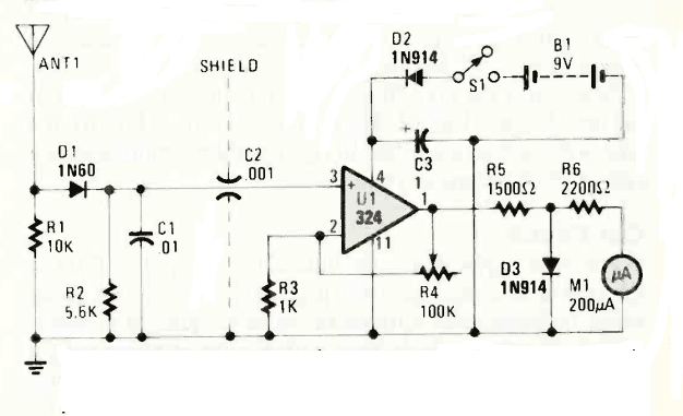
Radio frequency work can be tricky business, especially when you need to measure signal strength without the complexity of tuned circuits. Enter the untuned field strength meter (FSM) a simple effective tool that every electronics enthusiast should have in their toolkit.

What is an Untuned Field Strength Meter?
An untuned field strength meter is broadband RF detector that measures the strength of radio frequency signals without needing to be tuned. Unlike its tuned counterparts, this device responds to RF energy across a wide frequency range, making it incredibly versatile for various applications.
How It Works
The circuit operates on a simple principle: RF energy picked up by the antenna is rectified by the detector diode, creating a DC voltage proportional to the RF field strength. This DC voltage is then amplified and displayed on a sensitive meter.
The untuned nature means the circuit responds to any RF energy within its frequency range, typically from a few MHz to several hundred MHz, depending on the construction and component choices.
Field Strength Meter –Key Components & Their Roles:
- ANT1 (Antenna): This is your primary sensor, designed to capture the RF energy from the air. A simple telescopic whip antenna or even a piece of wire can work.
- D1 (1N60 Diode): This germanium diode acts as a detector (rectifier). Germanium diodes are often preferred for RF detection due to their low forward voltage drop, allowing them to rectify even weak signals. It converts the AC RF signal into pulsating DC.
- R1 (10K) & R2 (5.6K): These resistors, along with C1, form a simple voltage divider and part of the RF front-end, helping to shape the signal before it reaches the detector.
- C1 (.01µF) & C2 (.001µF): These capacitors are crucial for filtering. C1 helps to smooth out the rectified DC from D1, while C2 provides further filtering and coupling to the amplifier stage.
- U1 (LM324 Op-Amp): This is a versatile quad operational amplifier. In this circuit, one section of the LM324 is configured as a DC amplifier. It takes the very small DC voltage from the detector stage and amplifies it to a level suitable for driving the meter.
- R3 (1K) & R4 (100K Potentiometer): R3 sets a reference voltage for the op-amp’s non-inverting input. R4 is a potentiometer, acting as a sensitivity control. By adjusting R4, you can control the gain of the amplifier, allowing you to measure both strong and weak signals.
- R5 (1500Ω) & R6 (2200Ω): These resistors, along with D3, form part of the meter driving circuit. They help to limit the current through the meter and provide a suitable range.
- D2 (1N914 Diode) & S1 (Switch) & B1 (9V Battery): This is the power supply section for the op-amp. D2 is likely a reverse polarity protection diode, safeguarding the circuit if the battery is connected incorrectly. S1 is the on/off switch, and B1 provides the necessary 9V.
- D3 (1N914 Diode):This diode is placed across the meter M1, likely for meter protection, shunting excess current away from the delicate meter movement in case of very strong signals.
- M1 (200µA Microammeter): This is your visual indicator. The amplified DC voltage from the op-amp drives this meter, and its deflection directly corresponds to the strength of the detected RF field.
Field Strength Meter –Building Tips:
- Shielding: Notice the “SHIELD” dashed line. This indicates that the detector stage (ANT1, D1, R1, R2, C1) should be shielded from the amplifier section to prevent direct pickup of RF by the op-amp and ensure accurate readings. A small metal enclosure or a copper foil shield can work wonders.
- Component Selection: While specific part numbers are given, equivalent components can often be substituted. However, for D1, try to stick to a germanium diode for better sensitivity.
While this design hails from 1989, its principles remain sound today. In our modern world filled with RF energy from WiFi, cellular networks, and countless other sources, an untuned FSM can help identify and measure this electromagnetic environment.
| VK4FUQ Optimized sloper antenna for 3.5Mhz |
| DIY – Terminated End fed V antenna |
