Have you ever wanted to generate pure, smooth sine waves for your audio projects, testing, or just for fun? This classic circuit Sine Wave Oscillatorprovides a straightforward and effective way to do just that! Perfect for hobbyists and students, this design uses readily available components to produce a clean sine wave output.
What is a Sine Wave Oscillator?
In electronics, an oscillator is a circuit that produces a repetitive, oscillating electronic signal, often a sine wave or a square wave. A sine wave oscillator specifically generates a smooth, periodic oscillation that resembles the mathematical sine function. These are incredibly useful for various applications, from calibrating audio equipment to creating musical tones.
Let’s break down the different sections of this sine wave oscillator circuit:
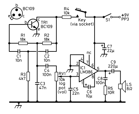
The Transistor Oscillator Core (TR1, R1, R2, R3, C1, C2, C3, C4)
This section forms the heart of our sine wave generator. It’s a phase-shift oscillator configuration, often a variation of a Wien bridge or phase-shift oscillator. TR1, an NPN transistor (BC109), acts as the active gain element, providing the amplification needed to sustain oscillations. R1, R2 (18kΩ), C1, C2 (10nF), R3 (4k7Ω), C3 (47nF), and C4 (100nF) collectively form the RC phase-shift network.
In a phase-shift oscillator, three (or more) RC sections are cascaded to provide a total phase shift of 180 degrees at the desired oscillation frequency. The transistor itself provides an additional 180 degrees of phase shift, leading to a total of 360 degrees (or 0 degrees), which is the condition for oscillation. These components also contribute to defining the oscillation frequency and providing stability.
Sine Wave Oscillator – Amplifier Stage (IC1 LM386)
Once the delicate sine wave signal is generated by the transistor stage, it’s often quite weak. That’s where the venerable LM386 low-power audio amplifier comes in. IC1, the LM386 integrated circuit, is a popular choice for small audio amplification projects due to its simplicity and effectiveness. It takes the low-level sine wave from the oscillator section and amplifies it to a level suitable for driving a small speaker.
RV1, a 10kΩ logarithmic potentiometer labeled “VOL,” acts as a volume control, allowing you to adjust the amplitude (loudness) of the sine wave output. C5 (22nF) is likely used for coupling the signal into the LM386 or for frequency shaping, while C6 (10µF) is typically used for gain control in the LM386 or for decoupling.
C7 (22µF) and C9 (220µF) are power supply decoupling capacitors, helping to smooth out the power supply voltage, preventing noise, and ensuring stable operation of the IC. C8 (100nF) and R5 (10R), connected to pin 5 of the LM386, form a Zobel network. This network helps to ensure amplifier stability when driving inductive loads like speakers, preventing unwanted oscillations or high-frequency ringing.
Power Supply and Output of sine wave oscillator
S1 serves as the main power switch for the circuit. The circuit is designed to be powered by a standard 9V PP3 battery, making it portable and easy to power. The “Key (via socket)” input suggests the possibility of modulating or controlling the oscillator using an external key or switch, perhaps to create Morse code-like tones. LS, an 8Ω speaker, is your output, where you’ll hear the generated sine wave.
Building Your Own – sine wave oscillator
This circuit is an excellent project for learning about oscillators and audio amplification. If you plan to build it, remember to stick closely to the specified component values for optimal performance. Ensure you create clean and solid solder joints. Pay close attention to the polarity of electrolytic capacitors (C7, C9, C6) and the correct orientation of the transistor (TR1) and IC (IC1). If you’re new to electronics, consider prototyping on a breadboard before soldering to a perfboard or PCB.
Sine Wave Oscillator – Applications
Once you’ve built your sine wave oscillator, its applications are diverse. You can use it for audio testing, generating precise frequencies to test speakers, amplifiers, and other audio equipment. It serves as a great learning tool to visualise and understand how oscillators function. With some modifications and controls, it could even be used as a basic building block for a simple audio synthesizer. The “Key” input suggests its potential use as a tone generator for learning or practicing Morse code.
This project offers a fantastic hands-on experience with fundamental electronic principles. So gather your components, get soldering, and enjoy the pure tones of your very own sine wave oscillator!
| Circuits – LM386 Audio oscillator |
| Mini FM Radio Transmitter |
