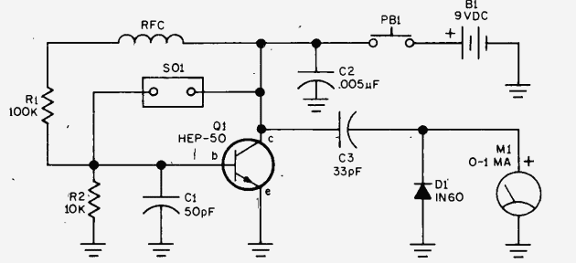
If you’re working with crystals and need a reliable way to test their functionality, a test oscillator circuit offers an effective solution. This crystal tester method lets you confirm a crystal’s “active” status by comparing its output to a known good crystal. Below is a refined guide based on a classic circuit design for building and using a crystal test oscillator.

Components Needed
Gather these precise components for the circuit:
- 9-volt transistor radio battery
- C1: 50-pF disc capacitor
- C2: 0.005uF 100 VDC or better
- C3: 33 pF 25 VDC or better
- D1: 1N60 diode
- M1: 0-1 mA DC meter
- PB1: Normally open push button switch
- Q1: 2N2222 NPN transistor
- R1: 100K, ½-watt resistor
- R2: 10K, ½-watt resistor
- RFC: 2.5-mH RF choke
- SO1: Socket matching the crystal type
The circuit centers around a transistor (Q1), with supporting components for stability and measurement. Assemble as follows:
- Set up R1 and R2 as a voltage divider for the transistor base.
- Incorporate the RFC for oscillator stability.
- Add the push button (PB1) and meter (M1) to monitor crystal activity.
Use a socket (SO1) that matches the crystal type. For versatility, consider adding multiple sockets in parallel to test different crystal types.
Crystal tester- Testing Procedure
To evaluate a crystal’s activity:
- Insert a known good crystal and press the push button (PB1).
- Record the meter reading as your reference.
- Replace with the test crystal, press PB1 again, and compare readings.
The meter reading should closely match the reference crystal. A significant deviation may indicate a faulty crystal. Use a reference crystal of the same type for accuracy.
For improved precision, add a 1000-ohm, ½-watt, 10% resistor in series with meter (M1) if needed. Ensure all connections are secure to prevent inaccurate results.
This test oscillator is a practical tool for hobbyists and professionals, enabling quick and reliable crystal testing. Ideal for radio repairs or electronic experiments, it helps maintain component quality efficiently.
